In this project, we’ll guide you through the exciting world of Arduino by showing you how to control three LEDs using an infrared (IR) receiver and a remote control. This practical project allows you to repurpose old remotes or add functionality to underutilized buttons.
Project Overview:
This project consists of two main parts:
- Decoding IR signals sent by your remote control.
- Using this information to control three LEDs with your Arduino.
Required Components:
- The heart of your project, the Arduino UNO is the brain that processes signals from the IR receiver and controls the LEDs. It’s the central control unit.
- Quantity: 1 Arduino UNO board.

- The breadboard serves as the platform for connecting and prototyping your circuit. It allows for easy and temporary connections
- Quantity: 1 breadboard.
- Use: Your existing remote control will be repurposed in this project. It sends IR signals to the IR receiver.
- Quantity: 1 Remote Control.

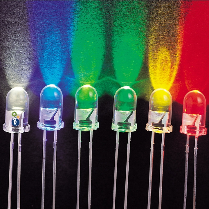
- Use: You’ll use three LEDs to demonstrate control. Each LED represents a different function, such as turning on or off.
- Quantity: 3 LEDs.
- Use:
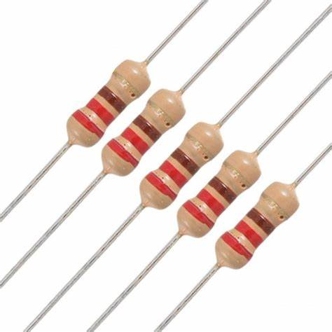
- These resistors are crucial for limiting the current flowing through the LEDs, preventing them from burning out when they’re on.
- Quantity: 3 220-ohm resistors.
- Use: The IR receiver, TSOP4838, detects IR signals from the remote control and converts them into electrical signals for the Arduino to process.
- Quantity: 1 IR Receiver.

- Use: Jumper wires are used to create electrical connections between components on the breadboard, ensuring that the circuit functions as intended.
- Quantity: Some jumper wires. The quantity may vary depending on your setup.

Introducing the Infrared (IR) Receiver:
The IR receiver, illustrated below (TSOP4838), is a key component for this project.
- First pin: Vout
- Second pin: GND
- Third pin: Vcc
When you press a button on your remote, it sends infrared signals. The IR receiver collects these signals, and each button corresponds to specific information.
Decoding the IR Signals:
In this step, we’ll decode the IR signals associated with each button on your remote control.
Schematics:

Coding:
To work with the IR receiver, install the IRremote Library in the Arduino IDE. Follow the steps in the code to receive and decode IR signals.
#include <IRremote.h>

int RECV_PIN = 11;

IRrecv irrecv(RECV_PIN);

decode_results results;

void setup()
{
  Serial.begin(9600);
  irrecv.enableIRIn(); // Start the receiver
}

void loop() {
  if (irrecv.decode(&results)) {
    Serial.println(results.value, HEX);
    irrecv.resume(); // Receive the next value
  }
  delay(100);
}
Controlling LEDs:
Now, let’s control three LEDs using your remote. Assign specific buttons for various LED tasks:
- LED1 – ON
- LED1 – OFF
- LED2 – ON
- LED2 – OFF
- LED3 – ON
- LED3 – OFF
Upload the code, then Press a button on your remote control, and you’ll see a code on the serial monitor. Take note of these codes; you’ll need them later.
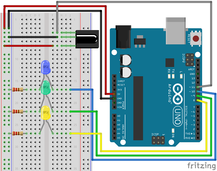
Building the Final Circuit:
In this section, we’ll build a circuit with three LEDs that can be controlled using your remote.
Schematics:
Follow the provided schematic to assemble all the components.
Coding:
Use the codes you captured earlier, converting them from hex to decimal using an online converter. Replace the hex values in the code with the corresponding decimal values.
#include <IRremote.h>

// Define pin numbers
int IR_Receiver_Pin = 11;    // IR Receiver Pin (Connect to pin 11)
int Blue_LED_Pin = 10;       // Blue LED Pin (Connect to pin 10)
int Green_LED_Pin = 9;       // Green LED Pin (Connect to pin 9)
int Yellow_LED_Pin = 8;      // Yellow LED Pin (Connect to pin 8)

// Create IR receiver object and decode results object
IRrecv irReceiver(IR_Receiver_Pin);
decode_results irResults;

void setup() {
  // Start serial communication
  Serial.begin(9600);

  // Enable the IR receiver
  irReceiver.enableIRIn();

  // Set LED pins as outputs
  pinMode(Blue_LED_Pin, OUTPUT);
  pinMode(Green_LED_Pin, OUTPUT);
  pinMode(Yellow_LED_Pin, OUTPUT);
}

void loop() {
  // Decode infrared input
  if (irReceiver.decode(&irResults)) {
    long int decodedValue = irResults.value;
    Serial.println(decodedValue);

    // Use a switch case to determine the action based on the decoded button press
    switch (decodedValue) {
      case 551520375: // When you press the 1 button
        digitalWrite(Blue_LED_Pin, HIGH);
        break;
      case 551495895: // When you press the 4 button
        digitalWrite(Blue_LED_Pin, LOW);
        break;
      case 551504055: // When you press the 2 button
        digitalWrite(Green_LED_Pin, HIGH);
        break;
      case 551528535: // When you press the 5 button
        digitalWrite(Green_LED_Pin, LOW);
        break;
      case 551536695: // When you press the 3 button
        digitalWrite(Yellow_LED_Pin, HIGH);
        break;
      case 551512215: // When you press the 6 button
        digitalWrite(Yellow_LED_Pin, LOW);
        break;
    }

    // Resume to receive the next value from the pressed button
    irReceiver.resume();
  }

  // Add a small delay to avoid excessive processing
  delay(10);
}
Wrapping Up:
This project is a fantastic way to explore the capabilities of an IR receiver. You can expand on this by replacing LEDs with relays to control household appliances, making your remote even more useful.

Leave a Reply